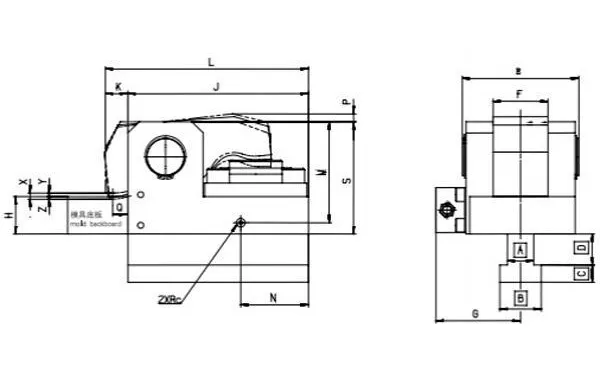
Technical parameter
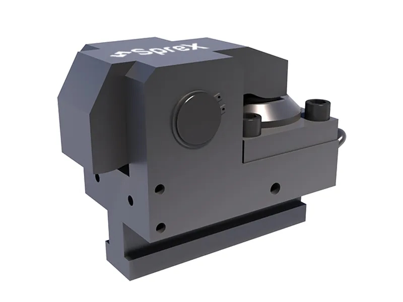
FW2
- Clamping force (25MP): 20 kn
- Stroke X: 7 mm
- Clamping stroke Y: 3 mm
- Reserved secure stroke Z: 4 mm
FW4
- Clamping force (25MP): 40 kn
- Stroke X: 7 mm
- Clamping stroke Y: 3 mm
- Reserved secure stroke Z: 4 mm
FW6
- Clamping force (25MP): 60 kn
- Stroke X: 8 mm
- Clamping stroke Y: 4 mm
- Reserved secure stroke Z: 4 mm
FW10
- Clamping force (25MP): 100 kn
- Stroke X: 8 mm
- Clamping stroke Y: 3 mm
- Reserved secure stroke Z: 5 mm
FW16
- Clamping force (25MP): 160 kn
- Stroke X: 8 mm
- Clamping stroke Y: 3 mm
- Reserved secure stroke Z: 5 mm
FW25
- Clamping force (25MP): 250 kn
- Stroke X: 8 mm
- Clamping stroke Y: 3 mm
- Reserved secure stroke Z: 5 mm
FW50
- Clamping force (25MP): 500 kn
- Stroke X: 8 mm
- Clamping stroke Y: 3 mm
- Reserved secure stroke Z: 5 mm
Optional type
| Type | Clamping force(25MP) | Whole stroke X | Clamping stroke Y | Reserved secure stroke Z | Hydraulic clamping cylinder volume | Weight |
| KN | mm | mm | mm | cm3 | kg |
| FW2 | 20 | 7 | 3 | 4 | 6.5 | 2 |
| FW4 | 40 | 7 | 3 | 4 | 13 | 4.8 |
| FW6 | 60 | 8 | 4 | 4 | 21 | 7.2 |
| FW10 | 100 | 8 | 3 | 5 | 33 | 13 |
| FW16 | 160 | 8 | 3 | 5 | 50 | 23 |
| FW25 | 250 | 8 | 3 | 5 | 88 | 36 |
| FW50 | 500 | 8 | 3 | 5 | 173 | 80 |
Type selection
Users can choose the corresponding clamp type and number according to their equipment needs.
| Machine Capacity | Specs of the hydraulic clamping system | Thickness of mold platen(mm) |
| Fixed platen | Number | Movable platen | Number |
| 60-120 | FW2 | 4 | FW2 | 4 | 25 |
| 160-250 | FW4 | 4 | FW4 | 4 | 30 |
| 280-320 | FW6 | 4 | FW6 | 4 | 30 |
| 350-600 | FW10 | 4 | FW10 | 4 | 40 |
| 650-850 | FW16 | 4 | FW16 | 4 | 50 |
| 900-1300 | FW16 | 6 | FW16 | 6 | 50 |
| 1400-1600 | FW25 | 6 | FW25 | 6 | 50 |
| 1800-2800 | FW25 | 8 | FW25 | 8 | 50 |
Features
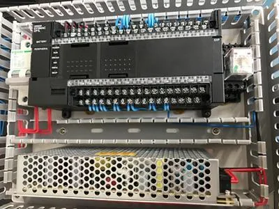
- The electrical system controller is equipped with an OMRON programmable controller, providing a user-friendly interface and multiple layers of safety protection.
- Designed with precision and reliability in mind, our hydraulic clamping system ensures optimal performance and ease of use.
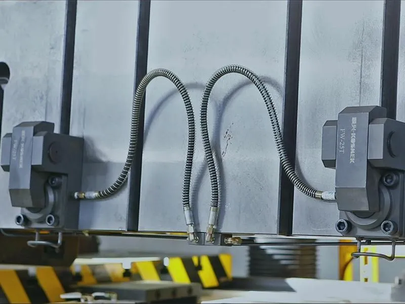
- The clamps are arranged in a diagonal pattern on the mold plate, and in doing so, there are 4 standalone oil lines on one pair of mold plates. If one line leaks, the other lines will not be affected.
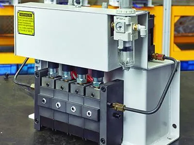
- The pump and manifold valve utilize zero leakage sealing technology, thus ensuring a leak free performance for up to 168 hours under 25MP system pressure.
- The pump station's power unit is a pneumatic booster pump from the Japanese company KOSMEK, and features a dual pump design to improve both the working stability and security.
- The system pressure is detected using four groups of pressure switches from the American company GEMS,. The powder unit will provide supplemental pressure when the system pressure is lower than the setting, thus ensuring the system pressure is controlled in normal ranges.
- This FW series hydraulic clamping system is equipped with a PLC controller from OMRON and electrical devices from SMC, thus ensuring a longer service life and a reliable quality.
- The hydraulic clamping system and injection molding machine feature a safety interlock function, which ensures a high degree of security during usage.
Dimensions
| Specification | G | E | F | S | P | Q | Rc | M | N | L | K | J | H(Standard) |
| FW2 | 60 | 58 | 28 | 58 | 6.7 | 12.5 | 1/4 | 48 | 24 | 100 | 18 | 82 | 25 |
| FW4 | 66 | 73 | 40 | 80 | 8.6 | 16 | 1/4 | 70 | 35 | 138 | 23 | 115 | 30 |
| FW6 | 80 | 94 | 50 | 87 | 8.3 | 20 | 1/4 | 76 | 45 | 160 | 30 | 130 | 30 |
| FW10 | 90 | 106 | 55 | 107 | 11.1 | 20 | 1/4 | 95 | 55 | 194 | 30 | 164 | 40 |
| FW16 | 100 | 126 | 60 | 135 | 8.6 | 20 | 1/4 | 120 | 75 | 230 | 30 | 200 | 50 |
| FW25 | 113 | 155 | 73 | 150 | 10.5 | 20 | 1/4 | 135 | 90 | 270 | 30 | 240 | 50 |
| FW50 | 155 | 230 | 110 | 178 | 10.5 | 20 | 1/4 | 160 | 90 | 320 | 30 | 290 | 60 |
Note: H is the thickness of mold base plates that are matched to a standard hydraulic clamp. Customization is available upon request.
Related Products

